Computer science research motivation was driven by the collaboration between European Union and United State in partnership with IBM Research to monitor cargo containers coming through ships – sea trade lanes. In 2003 close to 3% of the containers were monitored and their contents verified. The
so the project called “Secure Trade Lanes” was initiated to track the cargo containers throughout its supply chain from the source country storage facility, to the trucks carrying them to the docks, loading them to the ships, inside the ship hull, docking at the foreign counties on the way, unloading at destination and going through customs. The
when they are on the ship since regular means of network communications via radio frequency don’t work. This is the problem I worked with through guidance from my research adviser at IBM Research and
. We called it pervasive monitoring.
We came up with a data communication system capable of communicating via almost anything using a multi-channel physical layer consisting up of Radio and Acoustic. Next step was to come up with a bandwidth aware network layer multicast that can actively react based on feedback from the lower multi-channel physical layer. Hence the packets can scaled down in bandwidth either by spreading them in time or reducing the size itself. This allows us to transparently switch between multiple channels with varying data capacities. We applied this framework to the concept of Pervasive Monitoring. Related reports – “
Communication Through Almost Anything: A Step Towards Pervasive Monitoring” and “
Bandwidth Adaptive Multicast for Pervasive Monitoring”.
1. Introduction
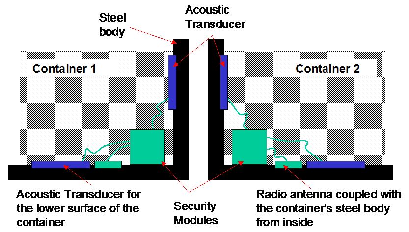 |
| Figure 1. Container to Container Communication |
We are moving towards an age where applications are
becoming distributed with need for device-to-device communication becoming an
important concern for system designer because of the complexity involved in
varying coverage range, medium of transmission, reliability and data rate requirement.
Application scenarios involving ad-hoc network collaboration and sensor
networks some time have the characteristics that it is not required to transfer
a large amount of data from one device to another. One such application is
monitoring a system using sensors attached to various sub-system components. If
we do most of the sensing computation at the sub-system level, then to get the
status of the device, each device need to send just a status message to the
central control unit. To make the system fault tolerant and secure a
modification would be to distribute the functionality of the central control
unit that keeps the status of the system. Pervasive
Monitoring is aimed at such a type of distributed system.
We use the Pervasive
Monitoring paradigm to keep track of
cargo containers in a ship hull. Asset
tracking in cargo ships has been a know problem. Once a cargo container leaves
its source, the container (while places in a ship/train/truck) should follow a
predefined path to its destination. Moreover, it should not be tampered on the
way. We attach security modules to each container that can communicate with
other container’s module via a communication channel. A centralized GPS [1] module (GPS beacon)
transmits the current location coordinates of the ship to each and every
container either directly or via other security modules. These can be buffered
by a security module and later accessed to tell the full path taken by that
container from its source to its destination. Each security module can
themselves generate the updates to indicate their current status. In this
paper, we concentrate on the over all design and implementation of the security
modules and the data communication model.
1.1. Communication
Medium
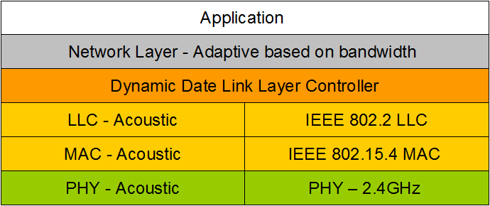 |
| Figure2/3. Communication Protocol Stack |
Radio Frequency (RF) has been widely used for
short/long range data communication in ad-hoc and sensor networks. They are normally aimed at high data rate
scenarios where a large amount of data needs to be exchanged. But this is not
the case everywhere, especially in pervasive computing environment. It may
sometime be sufficient to exchange just small amount of data between devices.
Another issue is that communication via radio may not be always possible. An
example is communication underwater, where RF is not the best carrier for data.
This is inherent in RF. Radio waves have the disadvantage that they can't
penetrate solid and liquids unless we use very low frequency. Very Low
frequency band (VLF) [2, 3] seems to be the solution, but antenna design
restrictions [3] make this solution less feasible for most applications, where
we can’t afford a very large transmitter and antenna size.
Sound (those hearable by humans) range from
frequencies of 20-20,000 Hz. Sound waves travel by creating compression and
rarefaction in the medium of propagation, which makes it possible for them to
travel via solid objects. Moreover, since sound is directional in nature, it
can be directed to only a specific receiver set giving added security. Sound
waves on one hand can travel via solids like steel, while on the other is
restricted by short coverage range. Radio wave does have long range, but lacks
penetration through solids. We go for a hybrid solution, where we use a multi
channel physical layer for communication consisting up of sound (acoustic) and
radio (RF).
1.2.
Setup
The
system consists up of set of steel containers arranged in three-dimensional
space in a ship hull. There is no fixed topology and at some places the
containers can be very sparsely arranged while closely stacked one over the
other at the other places. These with the help of the security modules form a
connected network, where each link between the nodes can be either acoustic or
RF.
There can be two types of containers (nodes) –
Containers with security module (those that needs to be tracked) and those
without security module (not to be tracked).
Containers with security modules are referred to as active nodes and can
communicate either directly to each other or via other active nodes. Active
nodes can receive, send and process messages. Containers without the security
module are referred to as the passive nodes. They only act as a passive
physical medium through which acoustic waves can travel. Figure 1 shows two containers fitted with the
security modules. Since sound is directional in nature, hence we need to have
an acoustic transducer for receiving and sending data via the acoustic channel
on every wall of the container. Hence a container will have 6 acoustic
transducers to take care of the 6 faces of the container. The radio antenna is
coupled with the container’s body.
A centralized GPS beacon is places at a single point
near the set of containers and is responsible for generating the Location Updates (GPS coordinates of the
ship). These are sent to every container in the monitoring network. A network
layer multicast ensures that the updates reach every node. We use the term node to refer to the active node in rest
of the paper.
1.3.
Requirements From the Data Communication Channel
We require a large data communication system that can
handle an ad-hoc network of nodes with similar processing capabilities but
varying link bandwidth. The physical channel can range from sound waves
traveling through steel as well as radio waves in air. The physical distance
between the nodes can vary tremendously from being few feets to as large as
1000 ft (typical length of a cargo vessel [4, 5]). The nodes have multiple
layers of steel containers (passive nodes) obstructing them from each other
with possibility of communication via small air gaps between containers or
through the material (steel in this case) of the container.
We cover details of the hardware/software
implementation of the security module prototype here. Section 2 explains the
communication model used for container-to-container communication via the
security modules. Section 3 covers the strategy to control the data rate based
on the available bandwidth, power constraints and connection state between
containers. Section 4 gives details of the implementation. Section 5 covers the
acoustic data communication module,
which is used in conjunction with the RF communication module to provide the
application with a multi channel physical medium.
2.
Communication
Model
Envisioned is a multi channel physical layer with a
dynamic data link layer controller (DDLL-C) layer merging the data link layers
of the two separate physical layers. Figure
3 shows the proposed protocol stack. Over the DDLL-C, the adaptive network
layer takes care of message routing and ensuring consistency of state table of
nodes in the monitoring network. An optional application layer can be used over
the network layer to build any custom application using the Pervasive Monitoring paradigm.
2.1.
Multi Channel Physical Layer
The physical channel is composed of a combination of
RF and acoustic. A possible solution for the RF is using the 2.4 GHz radio band
complying with IEEE 801.15.4 standards [6] for the MAC layer. We use IEEE 802.2
[7] for the LLC. The combination of 2.4GHz radio with IEEE 801.15.4/802.2 has
been widely accepted, and is commonly used for Zeebee [8] based transceivers. The Acoustic Layer is composed of a
typical acoustic modem [9, 10, 11]. The data rate achievable through the
acoustic link depends vastly on the modulation scheme we use. Currently, we are
planning to use a combination of Frequency Shift Keying (FSK) and Amplitude
Shift Keying (ASK) [12] to achieve a data rate of at least 400bps for the
acoustic communication channel.
2.2. Dynamic Data Link Layer Controller (DDLL-C) for
Switching between physical Layers
The basic principle is to switch from one physical
channel to another based on availability, while making sure that we use the
medium that provides the optimal compromise between the data rate available and
the power requirement of the node. Dynamic DLL Controller (DDLL-C) acts as an
interface to the network layer for the data service provided by the lower multi
channel data link. The main functionality of the DDLL-C is to:
- Interface to the
Acoustic and RF DLL.
- Inform the
Network layer about the data rates achievable through the next connected link.
2.3. Adaptive Network Layer
The network layer gets input about the bandwidth
available from the lower DDLL-C. Based on this, the messages can be scaled down
in size. For the current application, where we are monitoring a set of steel
containers for malfunction/tampering, the network layer consist up of an
adaptive multicast primitive that is able to forward the state change message
from a container to every other container. For location tracking, the network layer
also needs to ensure that the location coordinates from the GPS beacon reaches
every container’s security module.
Power usage at a security module will vary according to
the amount of data being transmitted over the network layer. Since the battery
power is limited at each node, the message size needs to be reduced even if the
lower physical layer can support that data rate. Section 3 describes a
framework for controlling the data rate the network layer by active feed back
from the lower layers about the battery usage and the bandwidth available (which
will vary according to the type of link available for communication).
3. Data Rate Control
based on Battery Power and Link
State
Bandwidth available to the network layer is dependent
on two factors, namely:
- Channel capacity
of the physical layer
- Power requirement
of the node
An
acoustic link between two nodes would mean a lower possible data rate compared
to a RF link. Additionally, it may not be possible to send the full message
through the RF/Acoustic link if the average power requirement to achieve the
same exceeds the average power required to maintain the system in operation for
the predefined period. The average power requirement will change tremendously
based on the type of link that is available at any particular point of time. An
acoustic link inherently consumes more power than a RF link. If the number of
passive nodes (steel containers in our case) between two active containers
using an acoustic link is increased, the transmitting node may have to increase
its transmitting power to enable the sound waves to travel a larger distance
without being attenuated too much. This increases the per bit transmission
power resulting in reducing the number of bits that the transmitter is allowed
to ensure the average battery power consumption level is maintained.
3.1.
Link Establishment and Maintenance
The transmitters in every node are capable of
adjusting their link signal strength of their transmitters. (Can be either the
acoustic or the RF transmitter). Starting at a minimal power level, the power
is increased until an acknowledgment is received from a node. Multiple
acknowledgements may be received if more than one node is nearly equidistant.
This establishes the connection(s). It is first tried using the faster RF link
and if that does not work, we move on to the acoustic link. When a node goes
down or a link is not operational, it silently goes down without notifying its
neighbors. There can be two cases:
- The current link that
went down was the only link connecting the node to the network
- There are still some
active links present connecting the node to the network
In the former, the node again needs to go through the
connection establishment phase till it finds an active link. In the latter,
nothing extra needs to be done. All this is handled by the DDLL-C on behalf of
the lower multi-channel physical and DL layers. Figure 4. gives the pseudo code for the part where a node needs to
send a message to it’s neighbor(s) (the message can either be generated at the
node itself or can originate from a remote
node that needs to be forwarded to its neighbors). If the node is not able to
connect within a predefined time (Timer.Threshold),
a panic alarm may be triggered while an event is logged in the local memory
space. We can also reset a status bit
that can be later accessed to indicate that the node was not connected to the
monitoring system for some amount of time during the monitoring lifecycle.
A message sent from a node is independent of the
receiver node. This enables us to transmit a message just once to all the
immediate neighbors. This saves on battery power. Moreover, this also enables
us to have a very large fanout (the
number of immediately connected neighbors), which we want as large as possible.
A high fanout enables the upper network layer to dissipate the location updates
to every node in the system in minimal time.
3.2.
Channel Selection
It will not always be possible to communicate via the
RF link. This may be the case if two containers are in a tightly packed set of
steel containers leaving no room for RF reception to reach the destination
container. Here, we will use the acoustic channel via the steel containers to
transmit data. Channel Selection is done by the DDLL-C by getting feedback from
the Signal Detector and Battery Power Meter (See Figure 6). If multiple
channels are available for data transmission, we choose a channel that is able
to send the message without the need for message queuing at the node. Moreover
we need to ensure that the transmitter power is kept to a level that the security
module can survive the whole life cycle of the monitoring phase.
Lets consider a channel x (which can be either
the RF or the Acoustic channel). We define the following parameters:
rx (bits per second): Data rate available via
the channel x
dx (bits): Size of the
message to be transmitted via channel x
U (updates per
second): Location Update Rate
Px (watts per bit):
Transmission power for channel x
Ex (watts.seconds):
Energy to transmit dx amount of data via channel x
neglecting any protocol overheads (for simplicity).
tx (seconds): Time needed to transmit a message
of size dx through
the link x.
We require that at each node, no updates should be
queued. i.e. as soon as a update arrives, it can be sent directly to the next
node without waiting for a pervious update that may have arrived earlier. Details for the modeling are available in request.
Using the modelling, we defined the function validatePowerReq (Figure 5), which takes
in three parameters responsible for indicating whether a message with a size can be transmitted through a given channel while ensuring
that the battery of the security module can survive the whole monitoring life
cycle with the current battery usage. ExtraplateBatteryReq
used in validatePowerReq takes in the current energy need and extrapolates the energy requirement of the node based on
the average power required so far. It returns a boolean value indicating
whether the asked amount of energy can be spent in transmitting the current
message while having enough energy for the system to survive the whole life
cycle of the monitoring phase. We can use
any extrapolation algorithm. Commonly used options are the Richardson
Extrapolation and variations like GREP (Generalization of the Richardson
Extrapolation Process), the d-Transform etc. Refer to [13] for details of these
methods. A simple approach can be to use averaging. We calculate the average of
the total energy consumed so far per update and check if this average will
suffice for the remaining updates. Total number of updates is calculated using
the Update rate, U and the remaining
time of the monitoring phase.
connectToNeighbors combined with validate gives the complete channel selection algorithm. This is shown in Figure 5. connectToNeighbors
starts by choosing the RF link while using minimal transmit power (MIN_PWD). If
the connection step (_connect) was
not successful, the power of the current channel is doubled. The updated power
level is validated (as explained before) using validatePowerReq. If this provides a positive answer, we use this
power level to connect via the current channel. If the current power level is
not allowed, we switch to the next channel (toggle(channel)).
The switching process is probabilistic. We control the probability (p) of switching from one channel to
another. Currently, we use p =0.6 indicating that in 60% of the cases we switch
back to the RF channel (which has more bandwidth compared to the acoustic
channel). Probability p is an
experimental parameter and can be varied based on performance.
3.3.
Data Scaling - Message Pruning
Since the links between the nodes are heterogeneous,
it may be required to scale down the message to make sure that the update can
be transmitted in a fair amount of time through a link. This may be the case
when an update moves from a Radio link to an Acoustic link. If the data rate
available at the Acoustic link is not enough to support the required location
update propagation rate (i.e. the incoming location update rate is more that
the rate at which the update can be sent forward – hence, the updates are being
queued temporarily), then data scaling needs to be performed to strip down the
update. Upward scaling is irrelevant in
our case since if the packet is scaled down at a link then the information lost
can’t be recovered. Hence if a high bandwidth link is available to transmit,
the packet is forwarded as it is.
Message Pruning
is done in such a way that in the
worst case, we are able to prune the message to consist up of just a single bit
(a status). We don’t cover the details of message pruning in this paper.
4.
Implementation
Details
Figure 6 gives the overall picture of the communication stack
with the hardware blocks needed to
implement the security module. RF Transceiver and the Acoustic
Trans-receiver are coupled with the Signal Strength Detector, which
itself provide the upper layers with the signal strength information. Battery
Power Meter interacts with the Dynamic DLL Controller to provide the
upper layer of the protocol stack with the information regarding the battery
usage.
4.1. Radio Data Channel
The radio transceiver can be implemented using one of
the Zigbee Chipsets [8]. A typical example for the 2.4 GHz domain is the Zigbee
solution from Motorola [14]. The advantage of operating at 2.4 GHz is that it
is a global frequency band allowing for one system design to be used worldwide. 2.4GHz radio with IEEE 801.15.4/802.2 (Refer to Figure
3) has been widely accepted, and is commonly used for Zigbee based transceivers. IEEE 802.15.4 based physical layer
operating in the 2.4 Ghz radio band can deliver data rates up to 250kbps. The
data modulation that needs to be used as mentioned in the IEEE 802.15.4
standards is 16-ary orthogonal modulation. The IEEE 802.15.4 MAC layer with IEE
802.15.4 LLC provides a reliable data link with the added advantage of
extremely low power requirements.
For the cases when it is not feasible to operate using
the Zigbee based RF link, the system switches to the acoustic data channel. We
present the detailed implementation of the acoustic channel in the next sub
section.
4.2. Acoustic Data Channel
Opposed to the high data rate achievable via the radio
data channel, acoustic data channel provides a low bit rate communication
medium. It consists up of an acoustic transceiver based on the concept of acoustic modems [15, 16, 17, 18, 19]. Transmission
range of the receiver depends on the power at which the acoustic transmitter is
operated. Since the transmission may need to span multiple steel containers, to
conserver power the transmitter should be in the transmitting state for minimal
time. Hence we need to go in for a data encoding scheme, where we keep the
symbol duration for the data to be low while keeping the encoding strategy
simple to keep the communication robust. Robustness is required because of the
noisy nature of the communication environment (the ship hull). We describe such
an encoding scheme next.
Data Encoding/Decoding
Frequency Shift Keying (FSK) [12] to encode 8 bit
symbols to harmonic audio frequencies [20, 21] provides an ideal solution for
data modulation on an acoustic carrier giving us data rate of 400 bps for a 20
ms symbol duration. Besides conserving batter power, keeping the symbol
duration low also helps in making sure that the sound produced is not annoying
to the human listener. By using FSK to encode bits in the frequency domain, we
also reduce the impact of echo[1]
and signal delay. FSK can combine this with Amplitude Shift Keying (ASK) to
encode more information in the amplitude. Although, ASK is not robust compared
to FSK, we can still use ASK to encode some complimentary information. An
example is to associate a group identifier with every container. Each container
can be considered as belonging to a group that can be based on the destination
where the container is going or/and the source of the containers. Hence we can
achieve a two level message identifying scheme, where containers can
distinguish between messages coming from containers within a group.
We now discuss the over all design of the transmitter
and receiver for the acoustic channel. Here we present a software based
approach where the modulator and demodulator of the transceiver is implemented
in software on a general purpose
processor or a specialized digital signal processor (DSP).
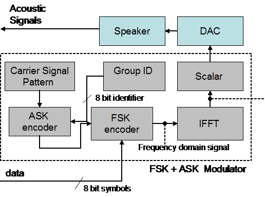 |
| Figure7. Acoustic.Transmitter |
Acoustic
Transmitter
Figure 7 gives the block diagram of the acoustic
transmitter with the software modules needed for the modulator. Besides the D/A
converter (DAC) and the speaker, the rest can be implemented in software. FSK
is used to encode data over acoustic carrier, by mapping data (8 bit symbols)
to 256 different harmonic audio frequencies. A 8 bit group identifier unique to
a group is assigned to every container and encoded in the signal using ASK. The
encoded frequency domain signal is converted to the time domain taking the Inverse Fast Forrier Transform (IFFT) of
the input. After proper scaling (via Scaler), the output of the IFFT, is fed to
the digital to analog converter (DAC) and finally to the acoustic transducer -
a speaker in this case. Care is taken to ensure that the speaker is linked to
the container walls in such a way that the sound waves are directional as far
as possible. This on one hand reduces the echoes, while on the other increases
the penetration dept of the acoustic waves generated.
Acoustic
Receiver
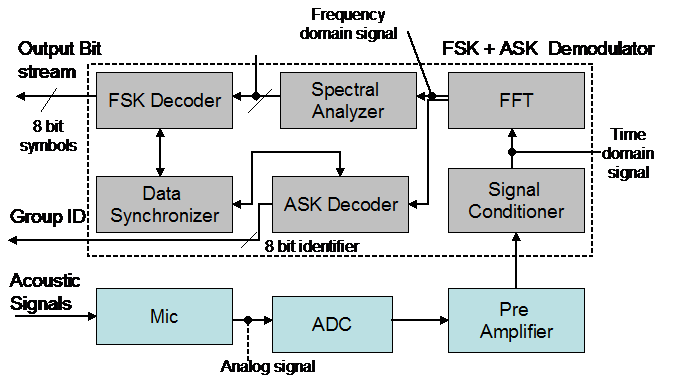 |
| Figure8. Acoustic Receiver |
A microphone attached to the containers outer walls is
used to receive the incoming acoustic signals through the steel containers. The
signal is sampled using the analog to digital converter (ADC) at a rate of 44
KHz (typical maximum sampling rate for the A/D converters present in portable
devices like PDAs and cell phones). The digitized
signal is amplified to normalize it to a pre-defined voltage range. The signal
may need to be conditioned to get rid of unexpected spurs and noises. Fast
Fourier Transform (FFT) is calculated to get the frequency domain
representation of the conditioned signal. The signal is then analyzed for
harmonic frequencies via the Spectral
Analyzer software module. It is responsible for checking the frequency
domain signal for harmonic frequencies that represent encoded data. The
recovered spectral information is decoded by the data decoder consisting up of
FSK Decoder and Ask Decoder. FSK Decoder is simply a mapping from the 256
different harmonic frequencies to the data, where each of the 256 harmonic
frequencies maps to an 8 bit symbol. Hence, the FSK decoder takes in a stream
of frequency values supplied by the Spectral Analyzer and outputs 8 bit
symbols. ASK decoder takes in the amplitude information recovered by the
Spectral Analyzer and maps that to a 8 bit Group ID. Since, the data decoder
needs to know when the symbol starts/ends, there needs to be some additional
padding information required in the signal. This information is used by the Data
Synchronizer to help the data decoder to identify the start/end of a symbol. Figure 8 gives the block diagram of the receiver.
The transducer (microphone), A/D converter (ADC) and the pre-amplifier are the
only other hardware components besides the processor that implements the
software modules (Data Decoder, Spectral Analyzer, FFT, Signal Conditioner)
4.3.
Dynamic Data Link Controller (DDLL-C)
DDLL-C act as an interface for the Network layer to
access the functionality of the lower multi channel data link (IEEE 802.15.4
and Acoustic DLL). The channel selection algorithm (as defined in Figure 5)
implementation also belong to this DDLL-C. DDLL-C gets information about the
available physical channel via the Signal strength detector (See Figure 6) and
power usage via the Battery Power Meter. Based on these two parameters, DDLL-C
determines whether the message with a size as requested by the Network Layer
can be forwarded to the next immediate connected neighbor.
4.4.
Software Defined vs. Hardware Acoustic Transceiver
Since we are using human audible frequencies for the
implementation of the acoustic data channel (20- 20,000Hz), it possible to
implement most of the hardware blocks for the Acoustic transmitter and receiver
in software. Based on the Nyquest Criteria [22], the ADC for the acoustic
receiver needs to sample at a rate of at least 40 KHz to ensure proper
reproduction of the input signal. This sampling rate is easily achievable via
the inbuilt ADC of any Digital Signal Processor or 16-32 bit processor. If we
go in for such a hardware setup, then we can implement the other blocks of the
receiver, namely signal conditioning, FFT, Spectral Analyzer in software
itself. The transmitter can follow on the same lines with everything being done
in software. The encoded output from the DAC can be directly fed to the
acoustic transducer (a speaker). Software Defined Radio [23, 24] has been
widely known to be flexible and future
proof.
If we go in for a purely hardware based solution for
the acoustic channel, the processing requirement is reduced tremendously. This
enables us to use any of the cheap 8 bit processors available in the market for
general processing (excluding the cryptographic functionality needed for
message validation, which is being handled by the separate crypto processor –
JCOP [25])
5.
Discussion
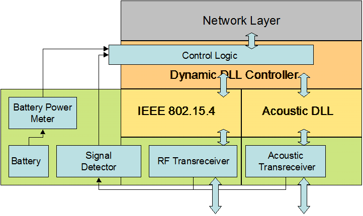 |
| Figure 6. Overall Security Module Architecture with Required Hardware Blocks and underlying protocol stack |
Pervasive
Monitoring can be applied in
multitude of application scenarios including security at home/office. System
events can be tracked in real time and logged. Industrial setups, where a
network of sensor is used to monitor the over all operation can use our
methodology. Asset tracking can be broadened not just to cargo ships, but
medical domain – hospitals. Tracking hospital assets can be an area which can
use the pervasive monitoring paradigm although the communication needs may not
that stringent. Inventory monitoring and tracking in big giants like Walmart or
COOP is another application area. Here timely and accurate report of inventory
is very essential for ensuing proper functioning. Data centers needs to
maintain a constant ambience temperature and hence need cooling system to be
controlled in a precise way. This is another scenario where we can use the
concept of pervasive monitoring.
[1] It
needs to be seen whether an echo cancellation scheme will be needed in our
system, where the acoustic communication is via solids and is highly
directional in nature.

 XMOHAN