For further read - Multi Channel AM Band Software Defined Radio - Pervasive Radio Receivers
Peer-to-peer Systems and AM Radio
Summary
At MIT Media Labs, I researched on inventing an architecture for AM band software defined radio, where the signal demodulation as well as tuning are both done in software. This makes the system flexible and future proof. We present a novel design for Pervasive Radio Receivers for AM band capable of receiving multiple AM stations. The receiver interface provides users option of simultaneously tuning to multiple channels, pausing a channel in real time and starting again from the point where one left from etc. The receiver user interface provides a visualization of the whole band showing the valid available channels making the system intuitive to operate. Applications involve use of Pervasive Radios in Internet connected cars to defence use. US Army can use the Pervasive radio receivers to modulate and encode the sensitive communication before sending it, where the RF signal modulation and encoding can change on a daily basis to make it hard for any hostile interception of the sensitive information. Since the demodulation is done in software, the demodulation algorithm can be changed on the fly via a software update to the army radio receivers.
Use Case
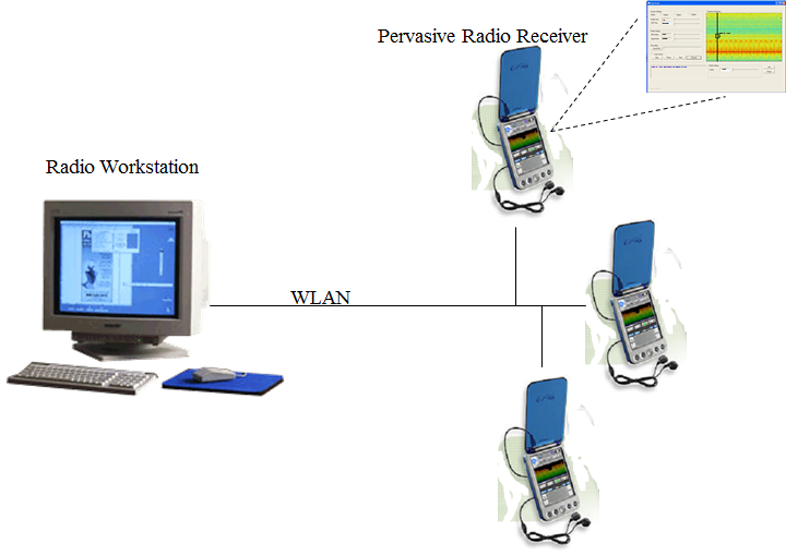
Imagine a scenario, where a group of people is driving in a car; each having his/her own PDA with attached earphones. One of listening to the local news at WBZ 1030; while another person is listening to his favorite music channel at WBPS 1150. The driver, while listening to WBPS, decides to listen to the current traffic update from WBZ. She pauses the current channel, opens up another channel and tunes in to WBZ. Once she got what she wanted, she closes the traffic update channel and starts listening to WBPS from the point where she left. All PDAs are connected to a central computer terminal via a Wireless Local Area Network (WLAN 802.11). The central computer is connected to the AM antenna and is responsible for relaying the AM channels to the PDAs via the WLAN.
Motivation
We are living in an age where the number of electronic devices that a person uses is increasing. The thrust is towards combining all these heterogeneous devices into an all connected pervasive computing environment. As indicated by Grimm et. al [7], application data and functionality need to be kept separate, so that they can evolve in a global computing infrastructure. Moreover with the number of different types of electronic devices with processing power growing, there needs to be a common system platform, allowing applications to be run across a variety of devices with heterogeneous computing capabilities. This calls for keeping the major processing to be done at the band hand, away from the front end user device. Satyanarayanan [8] characterizes a pervasive computing environment as one saturated with computing and communication capability, but so gracefully integrated with users that it becomes a "technology that disappear". We follow from the same motivation and focus on building something that can "weave themselves into the fabrics of everyday life" [9]. Pervasive Software Radio is a step in that direction.
The advantage of using AM Band is that the frequency range is low enough to directly sample the incoming radio signals. This eliminates the need for an IF stage, which would be needed if twice the maximum frequency of the input signal [10] was more than A/D converter's sample rate. In our prototype, we are using a 12-bit ADC with a maximum sampling rate of 20MHz, thus eliminating the need for a hardware down-conversion of the input carrier frequency.
AM Band has been gaining momentum with the introduction of the Digital AM broadcast [12]. For many national and international broadcasters, AM band is the only option (frequencies below 30MHz). With the introduction of Digital AM broadcast, the problem of fidelity faced by the AM Band has been removed. This opens up new doors for use of the AM band for high fidelity radio as well as data communication.
Related Work
Considerable amount of work has been done related to wideband DSP based software radio as well as those based on general-purpose processors.
Speakeasy, a software radio architecture for US Military, [1] was one of the first software defined radio systems, referred to as the Spekeasy Multiband Multimode Radio (MBMMR). The main motivation was to come up with a joint service platform that could perform the functions of 15 existing military radios. The motivation for project came from the incompatibility of the communication equipment problems faced by the United States Military in the Grenada conflict. Later in the Operation desert storm as a large number of allies and coalition forces performed joint operations. With a single software upgradeable radio, the system was able to eliminate parallel maintenance, allow constant upgrades as technology advances, fault tolerance and survivability. It is based on a multiprocessor architecture that allows the major functions to be organized in any required processing sequence dictated by the waveform structure. This resulted in a all-digital, software programmable multi-band (2 to 2000MHz) radio system.
[2] brings out architecture for software radio with wide band capabilities with emphasis on the digital front end of the receiver. Analog to Digital converter imposes the design restriction for the over all design of the software radio receivers. With an upper limit on the sampling rate imposed by the current generation of ADCs, it becomes essential to have a hardware down conversion stage. [3, 4] talks about few of these restrictions and gives insight in the design of software radio receivers based on these restrictions. In our case, the maximum sampling rate required is 4MHz. Since we are using an ADC capable of sampling at a maximum rate of 20MHz, the need for a hardware down-converter stage doesn’t arise.
Software tuning turns out to be most computationally intensive module in the software-defined radio. [5] provides efficient ways for extraction of a narrowband channel from a wideband input signal. It provides algorithms ways to decouple the effect of interference rejection from SNR improvement while improving the computational efficiency of filtering by using only a subset of the input samples. The implementation of this algorithm exists in the wideband software radio system developed as part of the SpectrumWare [6] research project at MIT Lab for Computer Science.
SpectrumWare project provided a software-oriented model of the wireless communications. The main focus of the project was to temporally decouple the sample incoming data streams from the software modules. This enabled to do most of the processing to be realized within virtual time programming environment. SpectrumWare approach utilizes wideband sampling, and temporal decoupling to enable the software processing of RF signals on conventional platforms. Temporal decoupling of the input data stream allows the samples to be processed in large blocks making it possible to leverage from any statistical behavior in the input signal.
System Overview
The system consists up of a workstation acting as backend radio server. It is attached to an AM band antenna via a PCI Analog to Digital converter card. Tuning and demodulation is done all in software using the workstation’s processor. Using an off the shelve workstation instead of a dedicated DSP has many advantages. A workstation is more flexible in hardware with more memory and processing power making the system capable of handling more complex algorithms. Moreover economic and market factors because of the generalized nature of the workstations hardware results in reduced cost and fast commercial deployment. Bose et al [11] brings out factors that indicate that overall, a workstation gives better performance over a DSP. It also states that being general purpose, it reduces overall development and integration time with high-level applications.
We use a conventional AM antenna with a build in active wide band-pass filter. We amplify the input signal to make it in the range of the ADC. Everything including channel tuning and demodulation is done in software using the workstation’s processor. A Workstation acts as the central server, which can be accessed by a client device (Software Radio Receivers). Since all the processing and RF hardware lies on the workstation, so the client devices can just act as dumb devices with a common interface to access the Radio Workstation.
Below we present the architecture of the Digital Receiver, namely the RF Front End and the Software Tuning and Demodulation module. Section 6 brings forward the User Interface.
Digital Receiver Design
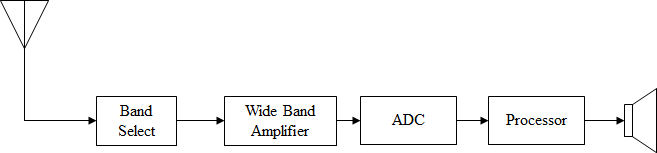
We use a conventional AM band antenna to get the AM radio signals from the air. The first step is to attenuate the unwanted frequency bands. We use a band-pass filter (Band Select in Fig. 2) with a central frequency at about 900 Khz and a frequency response that is relatively flat at the peak. We need to make sure that the signal other than the AM Band (~ 400 to 1400 KHz) are attenuated considerably to not have enough energy left to interfere with the AM Band. The output is amplified and then digitized using an Analog-to-Digital converter attached to the computer. The computer is responsible for tuning to the required channel, and then demodulating and later playing the tuned AM channel.
RF Front End
The RF front end is composed of the AM antenna, Band Select and the Wide Band Amplifier. Band Select is a band pass filter with a relatively flat response at its central frequency. The cutoff frequency is chosen as the centroid of the frequency range of the AM band. (i.e. ~900KHz ).
Antenna Design - Leaky Coaxial Cable Antenna
We started by using a conventional AM Band indoor antenna. The antenna was placed inside the building of the Media Labs premises. Since the building is shielded by aluminum-tiles from outside, the AM reception was poor. Hence we needed a way to break this artificial barrier to the RF signals and extend the RF signals inside the building. A very simple alternative is to just get the antenna out of the building and run a dedicated wire all the way to the workstation. But this approach will limit the number of workstations who can make use of the antenna to only one. We plan to use the Leaky Coaxial Cable Antenna [13] for our system.
Leaky Coaxial Cable (LCX) allows wireless pager, cellular phone, wireless fire-fighting telecommunications, car phone, broadcast reception and wireless communications services in the areas such as tunnels, subways, basement and underground markets, where ground radio waves can not pass. With slotted external conductor, this cable leaks the radio waves with stable characteristics.
With an outdoor antenna in place, the Leaky Coaxial Cable can run all the way in the building making the outside RF world visible to the internal antennas. Thus making it possible to use a conventional indoor antenna at the RF front end.
Band Select
Before we process the incoming RF signal, it needs to be trimmed to get rid of the unwanted frequency bands. Ideally we would like to have a wide band pass filter that filters out everything beside the AM Band (~400 to 1400 KHz). Currently we are using an active band pass filter built in the Indoor antenna itself. Although this is not the ideal solution, but it work for our purpose. The antenna allow us to set the cutoff frequency anywhere between 400 through 1400 KHz. We set the cutoff frequency in the middle of the AM band.
Wide Band Amplifier
Once we have removed the unwanted RF signals from the input, the signal needs to be amplified to the right signal level so as to make it possible for the ADC to digitize the signal. We have use an active multiple op-amp based solution for the amplifier. The gain achieved is about 50 (Vout/Vin) to get an effective voltage level of 2 volts peak to peak at the ADC input.
Automatic Gain Control
The RF gain control helps to you stop the inter-channel bleed caused by excessively strong signals. It limits the amount of signal getting into the radio to prevent the front end of the radio from being overloaded by a strong signal on a nearby channel. By using automatic gain control for the AM band, we increase our gain of the Wide Band Amplifier to a higher value. This will enable us to make use of the full voltage range of the ADC (for the current ADC, this range is ±5 volts). This makes sure that even the weak AM channels have a fair enough voltage level for the ADC to sample it with high enough fidelity. Current implementation does not include AGC, but will be included in the later versions of the prototype.
Software Tuning and Demodulation
 |
| One channel |
 |
| Multiple channels |
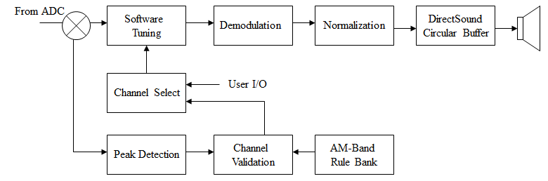
We use PCI-DAS4020/12, a 12 bit analog to digital converter from Measurement Computing to digitalizing the input RF signal. The ADC is able to sample at a maximum rate of 20MHz with a voltage range of ±5, or ±1 volts). We take in the input signal data in small chunks (10mses each). This ensures that we are able to do the entire signal processing in real time. Once tuning and demodulation of an input chunk of data is done, it is fed to the DirectSound buffer for playback. This ensures the continuity of the audio signal as we are playing the demodulated signal.
Narrow Band Tuning
To extract the narrow-band channel from the wide-band input signal, we use a FIR1 filter designed using Matlab's Signal Processing Tool Box. Since the input signal duration is just few mille-seconds (10Msec), hence we are able to use a relatively high order FIR1 filter while still maintaining very low latency between the input and the output audio playback of the demodulated signal. A high order FIR filter helps in making sure that there is a sharp transition between passband and stopband to reject adjacent channel interference. The second effect of using a high order FRI filter is that we are able to achieve a high SNR[1].
AM Demodulation and Sound Playback
Once a particular channel is extracted from the wide band signal, demodulation of the amplitude-modulated signal is done. The demodulated signal is normalized and fed into the Direct Sound buffer. We are using Direct Sound APIs for sound playback. We are using Direct Sound’s streaming buffer class to playback the demodulated audio. A streaming buffer plays a long sound that cannot all fit into the buffer at once. As the buffer plays, old data is periodically replaced with new data.
Both the Narrow Band Tuning and Demodulation modules are implemented in Matlab. To include these modules in our base project (VC++ project), we make a shared library of the Matlab code and use that library in the Microsoft VC++ code that we are using for developing the interface.
Valid Channel Detection
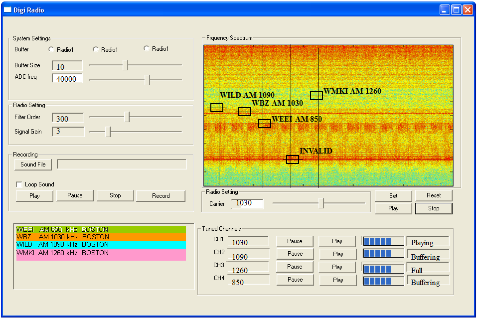
We also expect to do valid channel detection in real time, where we display the currently available valid channels in the AM frequency spectrum. The idea is to do peak detection in the frequency spectrum of the input signal coming from the A/D converter. We pre train the system with characteristics of a valid AM channel and later use this to select valid channel from the pre selected channels obtained in the peak detection phase. This is shown in figure 3.
User Interface
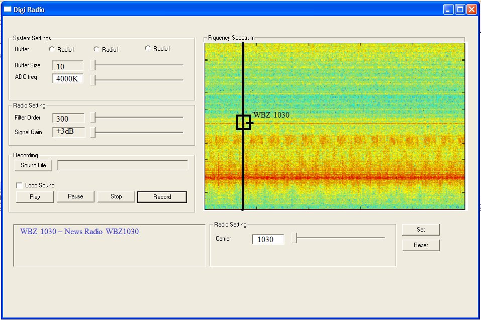
Figure 4 gives a snapshot of the proposed user interface for the Pervasive Radio Receivers. The first two sets of control are for the overall Radio Workstation, which may or may not be provided in a typical user-end Radio Receiver. One can control the buffer size of the Direct Sound buffer and the A/D sampling frequency. The filter order of the FIR1 filter and signal gain can be controlled through the second set. The user can record what he is listening in her local storage and play it later through the third set of control boxes. We also list the valid radio stations available with the radio workstation. The user can use the Radio setting control box to tune in to anyone of the available channels. She can even tune in to any other channels even if they are not listed.
The interface also gives a visualization of the frequency spectrum of the RF input. The spectrum is for frequencies from 0 till 2MHz (we are sampling at 4MHz in our prototype, so we limit our valid frequency spectrum to a maximum of 4MHz). All available channels are marked on the spectrum visualization. An experienced user can pick out the available channels based on the spectrum color coding (red for high energy carrier, colder colors for low energy carrier) itself and will not need the valid channel indicators.
User can tune in to multiple channels at the same time and pause a few channels while listening to a particular channel. The interface gives option of tuning in to 4 channels simultaneously. The pause time for any channel is limited and is governed by the fixed buffer space available to that channel at the Radio Workstation. The interface provides option of tuning to a channel, pausing it and placing it in the “Tuned channel” control box.
[1] Signal
to noise ratio
 XMOHAN